Description
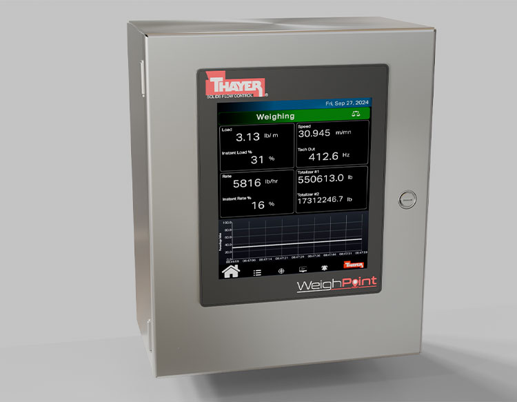
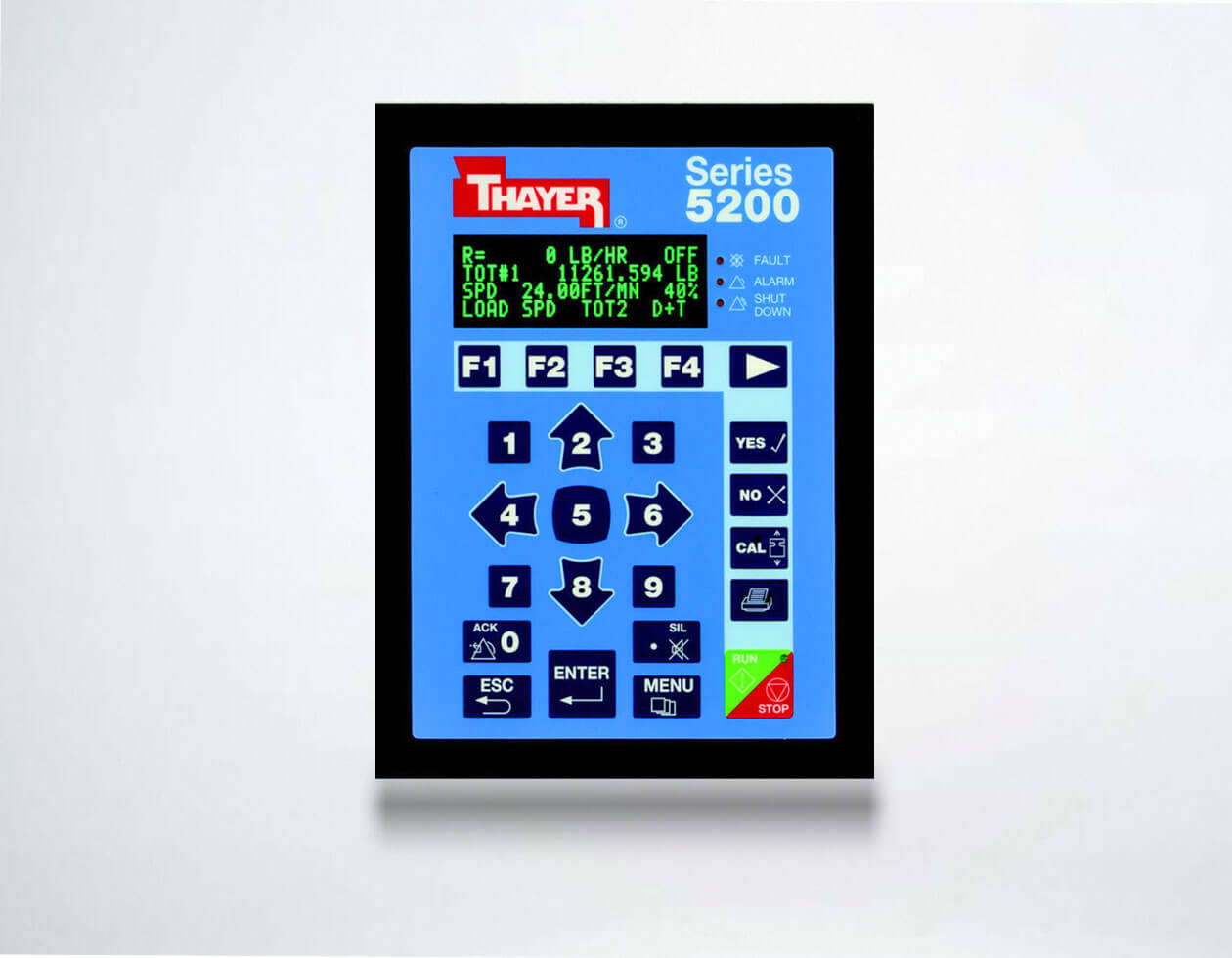
Series 5200 Enhanced Capability Weigh Belt or Loss-In-Weight Controller and Integrator
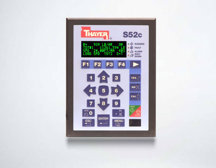
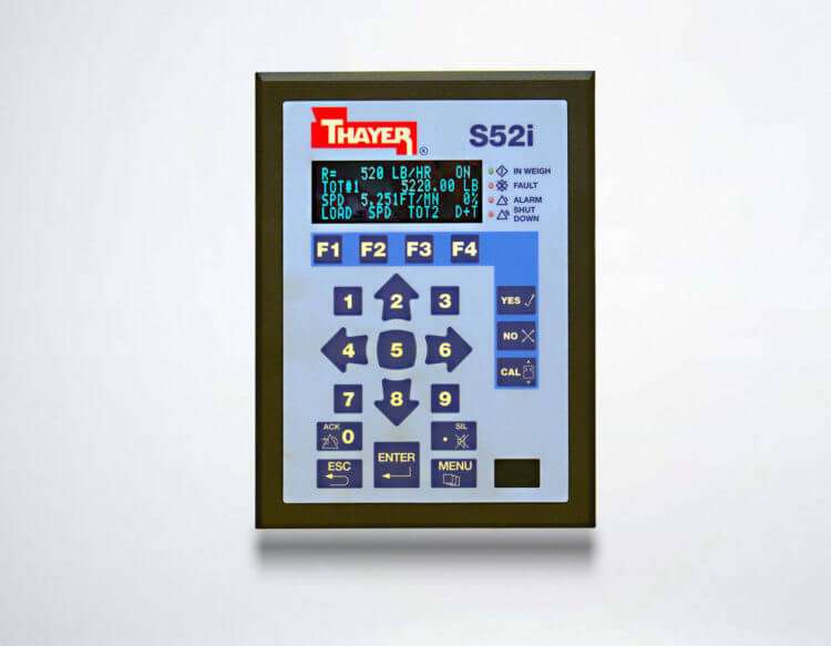
The Series 5200 Instrument is designed to operate as an integral part of a weighing system to provide continuous information on material flow for external use. The Series 5200 instrumentation is comprised of four components: the Central Processing Unit (CPU) which includes the Application software on a Flash memory card, the Scale Unit (SU-5200), the Operator Interface (OI-5200), and the Scale Junction Box (SJB-5200). Accuracy in weight and speed signals, flexibility in both I/O assignment (user assignable) and system layout (CPU, OI-5200 and SU-5200 can be separated or mounted to the conveyor frame), and an intuitive display/keypad that makes the system easy to use are among the features that set the Series 5200 ahead of the competitors.
Secondary Lever System

Input Power Requirements
| – Voltage Range: | 120 to 240 VAC |
| – Frequency Range: | 50 to 60 Hertz |
| – Phase Requirement: | Single Phase |
| – Power Consumption: | 350 W |
| – Supply Protection: | Fused |
Environmental Requirements
| – Area Classification: | Non-Hazardous |
| – Operating Temperature: | 14 to 158° F (-10° to +70° C) |
| – Operating Humidity: | 10 to 90% Non-Condensing |
| – Storage Temperature: | -4 to 185° F (-20° to +85° C) |
| – Storage Humidity: | 5 to 95% Non-Condensing |
| – Vibration Continuous: | 10 <= f <= 57 0.0375 mm Amplitude 57 <= f <= 150 0.5 g Constant |
| – Vibration Occasional: | 10 <= f <= 57 0.075 mm Amplitude 57 <= f <= 150 1.0 g Constant |
| – Shocks: | 15 g, 11 Ms Half-Sine in Three Axis |
| – Altitude Operational Up to 2000 Meters | |
| – Altitude Storage Up to 3000 Meters (70 kPa) | |
Standard Dimensional Requirements
| – Open Chassis: | Type IP23, 13.0″ H x 11.0″ W x 6.0″ D (330.2 x 1279.4 x 152.4 mm) |
| – Enclosed: | Type IP66, 13.8″ H x 11.8″ W x 7.9″ D (350 x 300 x 200 mm) |
Agency Approvals
| – Underwriters Laboratories, UL File #E208487 | |
| – NTEP |
Interface Communication Requirements
| – Isolated RS-422/485 4000 Wire Feet Max to SU-5200 | |
| – Isolated RS-422/485 4000 Wire Feet Max to Remote OI-5200 |
Standard Input/Output Specifications
– Analog Output:Isolated 4-20 mA into 750 Ohm Load Maximum
Sourcing, +24 VDC Compliance Voltage, Range 0-24 mA
AO-1 Programmable, Field Selectable
| – Analog Input: | Isolated 4-20 mA into 750 Ohm Load Maximum Sourcing, +24 VDC Compliance Voltage, Range 0-24 mA AO-1 Programmable, Field Selectable |
| – Digital Inputs: | Require Dry Contact Closures Sourcing, +12VDC with 10 mA Minimum Sink Current DI-1 Discrete – Drive Status DI-2,3,4 Programmable, Field Selectable |
| – Digital Outputs: | Isolated Relay Outputs Max. Voltage 240 VAC/VDC, Max. Current 120 mA Fault Discrete – System Fault (Form C) DO-1,2 Programmable (Form A) DO-3,4 Programmable (Form C) Totals 1 Discrete – Totalizer 1 (Form A) Totals 2 Discrete – Totalizer 2 (Form A) |
| – Frequency Output | Transistor Output, Range 0-25 KHz |
| Minimum Sink Current | Sourcing, +24VDC with 10 mA |
| Frequency Programmable, Field Selectable |
Expanded Input/Output Specifications
| – Analog Outputs: | Isolated 4-20 mA into 750 Ohm Load Maximum Sourcing, + 24 VDC Compliance Voltage, Range 0-24 mA AO-2 Programmable Field Selectable Typically Drive Output on Controller Applications |
| – Analog Input: | Isolated 4-20 mA Sinking, Input Impedance 169 Ohm AI-1 Programmable Field Selectable AI-2 Programmable Field Selectable |
| – Frequency Input: | Isolated Transistor Input, Range 0-25 KHz Sourcing (+5VDC) or Sinking (Range 3-24VDC) Frequency Programmable, Field Selectable |