Description
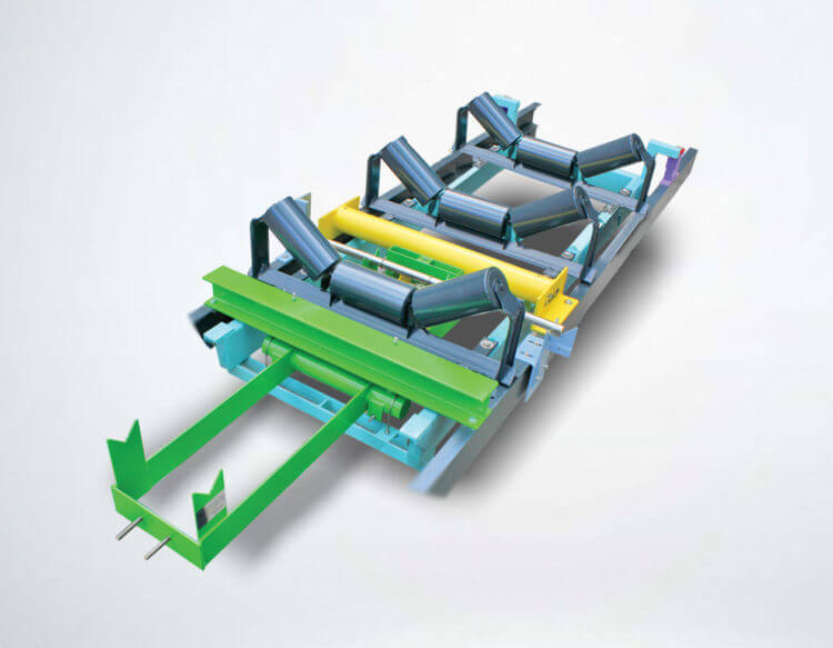
4NAR-6 NTEP Certified Conveyor Belt Scale
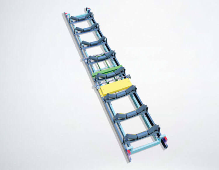
The THAYER NAR Belt Scales are designed to deliver exceptional stability and accuracy for use in applications requiring verifiable accuracy. They are recommended for applications requiring commercial certification for billing purposes. These Belt Scales have been proven in service demanding ±0.125% accuracy through independent certification. The weigh bridge features exclusive rocking flexure suspension in the approach-retreat configuration. Measurement sensitivity is high, deflection is low, and the load cell is isolated from the error-inducing effects of extraneous lateral forces, off-center loading, foundation distortion, inclination hold-back forces, and high sporadic shocks and overloads. Tare load is mass counterbalanced to create superior signal to noise ratio in weight sensing, orders of magnitude better than belt scale designs supporting full tare load on the load sensor.
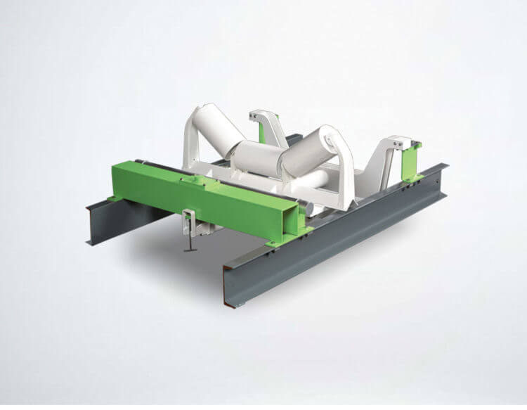
WEIGH BRIDGE
One of the most important components of a conveyor scale system is the design of the weigh bridge itself. Regardless of the type of load cell used, a belt scale will not be able to weigh lightly loaded material and maintain its calibration for long if certain design features are not in place.
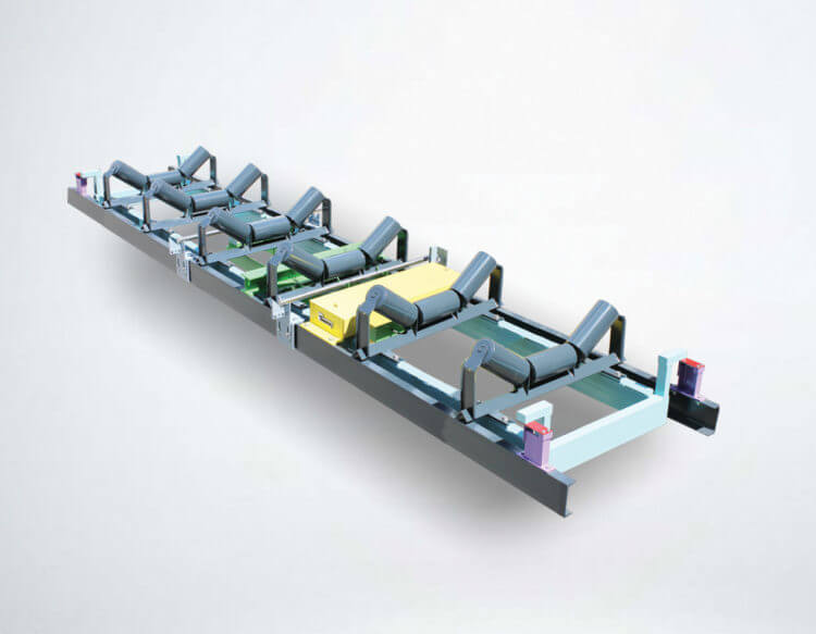
Secondary Lever
THAYER employs a secondary lever system, even though it cost more to do so, because it permits the following:
1. We can add mass (weight) to counterbalance the dead load (idler support frame, idlers, belts) and by using a secondary lever, we do not load down the suspension pivot.
2. The scale provides for complete mass counter-balancing of the dead load (idlers and belt) of the conveyor permitting the load sensor to react only to the net material load.
3. By positioning the load cell correctly, relative to the secondary lever we can match load cell size to the net loading. Only in this way can any capacity scale be supplied to the same high accuracy standards.
4. The resulting increased lever ratio of the secondary lever reduces idler deflection, providing additional immunity to errors associated with belt tension.
5. The secondary lever system utilizes stainless steel aircraft cables as flexural elements to transmit and FOCUS pure tension forces to the load cell. The cables, being non-extendable, but laterally yieldable connecting links, permit the lever to align itself under conditions of varying stringer distortion. This is a most significant feature. A belt scale must use the conveyor stringers as its mounting base. These stringers not only deflect under varying conveyor loads, but may also rotate (or twist). A suspension system having the least possible structural redundancy is therefore essential.
6. This unique system is not affected by dirt, shocks or vibration, and can withstand overloads in excess of 1,000 pounds without causing damage or affecting calibration.
THAYER Load Cell Utilization Factor

THAYER’S RF Flexure Suspension (patented)
The axis position is permanent, being held in its horizontal position by the flexure plate and in its vertical position by the load rod which bears on the flexure plate, which in turn is bolted to the bottom side of the square and elevated suspension extension shaft.
There is insignificant rotational hysteresis. While the load rod may be likened to a dull knife edge (it is round), the flexure plate bearing surface directly in contact can rock without sliding through small rotational displacement.
The reaction to lateral forces creates an insignificant moment transfer to the weigh suspension (this is part of the patent). Since the flexure plate (which is hardened blue tempered steel) is also the upper bearing block of the pivot, tensile or compressive forces reacting to lateral forces therein have no moment arm distance to operate.
The Model LC-174 NTEP Certified Load Cell is a Strain Gauge “S” Beam Load Cell that is housed in an enclosure that has identical mounting dimensions to that of the LC-137.
Available in force ranges from 25 to 2,000 lbs with an overload protection of 300% of rated output.
Precision Belt Speed Measurement
Accurate belt speed measurement requires the use of a precision wheel and pulser. A spring is used to maintain proper contact pressure of the wheel with the tension side of the belt in all operating conditions. The THAYER belt travel pulser assembly includes a precision cast/machined wheel with a “pre-calibrated” circumferential tolerance of ± 0.05% and a high resolution digital transmitter. The transmitter produces pulses equivalent to 1/100 to 1/200 of a foot of belt travel. The speed pick-up wheel has a narrow face width so it is less susceptible to material build-up, which can result in speed measuring errors. Since belt stretch is not constant throughout the length of the conveyor, and therefore, can affect speed measurement, the speed pickup produces a more accurate speed signal than that which is produced by tail pulley mounted speed encoders.

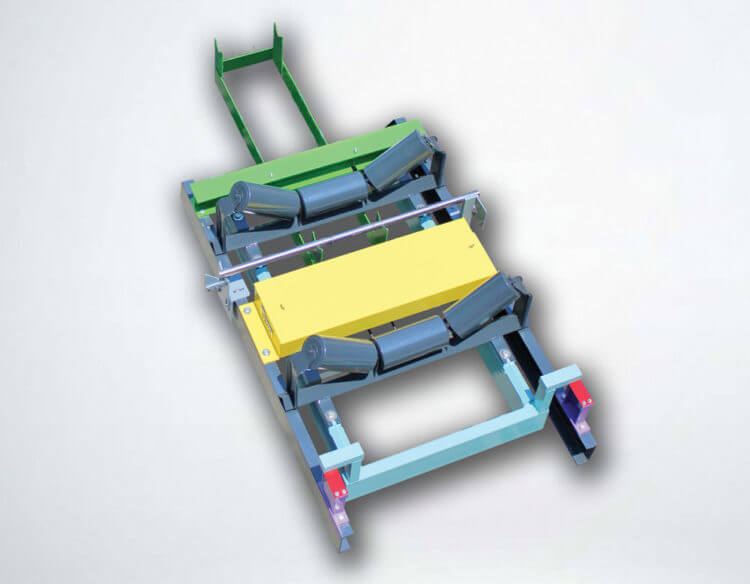
Thayer Test Weight Using “See-Saw” Secondary Lever

On high capacity scales where it is impractical to apply the test weight directly to the end of the weighbridge because of the physical size of the test weight, a special arrangement of the secondary lever is used.
In this configuration, the test weight provides tare mass counter-balance in its “storage” position on the secondary lever and a test load of known value in its “calibrate” position. By taking advantage of ratios in the secondary lever, smaller, easily manageable test weight(s) can be used to produce significantly higher loading values. This method of applying the test weight does not introduce error on inclined conveyors. Since the test weight is on the scale at all times, its moments due to the sine component remains constant regardless of the test weight’s position on the lever.
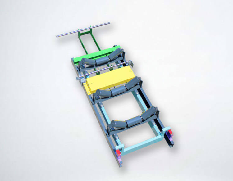
The weight is always present on the secondary lever, which also serves as a means to counterbalance dead loads and control the force range presented to the load cell. In the movable poise weight design the weight resides in either one of two locating “V” notches, but is never added or subtracted from the lever itself.
In one position, the weight serves as “counterbalancing” weight for a portion of the dead load. In the other position, the weight serves as the calibration test load. This unique method, whereby the movement of the weight alone affords the means to apply a large effective test load, is the only practical and economical system known for calibrating “heavily loaded” conveyor scales.