Description
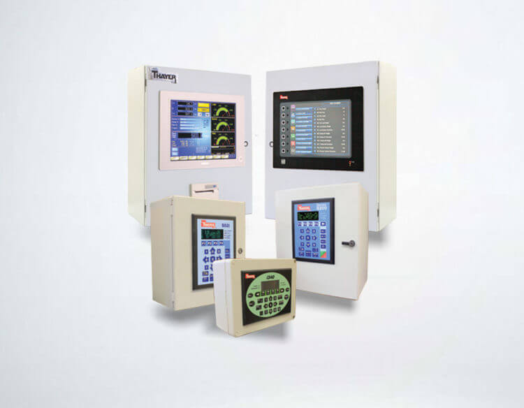
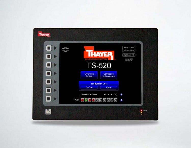
S52c WEIGH BELT or LOSS-IN-WEIGHT CONTROLLER
The S52c Instrument can be used on most Weigh Belt and Loss-In-Weight Feeder systems to provide continuous control and information about the flow of material to its process by monitoring the load and speed. The weigh system can use either a strain gage or LVDT Load Cell to sense weight; however a variety of sensors can be used to sense the speed.
Weight information on a Weight information is processed as weight per length and speed is processed as unit length per time. Integrated together, this information is processed by the controller portion of the instrument to provide continuous control of the system to match a target flow rate or set-point.
On a Loss-In-Weight application the S52c uses the change in weight of the feeder to determine instantaneous material flow rate and accumulative weight total information. The speed is used to control the feeder when in volumetric control, used during refill and disturbance control integrated together, this information is processed by the controller portion of the instrument to provide continuous control of the system to match a target flow rate or set-point.
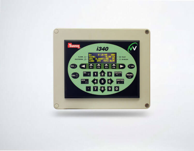
All information gathered by the system is then presented both visually on the instrument’s face and through optional communications via a number of field buses.
Input Power Requirements
| – Voltage Range: | 120 to 240 VAC |
| – Frequency Range: | 50 to 60 Hertz |
| – Phase Requirement: | Single Phase |
| – Power Consumption: | < 43 W |
| – Supply Protection: | Fused |
Environmental Requirements
| – Area Classification: | Non-Hazardous |
| – Operating Temperature: | 14 to 149° F (-10° to +65° C) |
| – Operating Humidity: | 10 to 90% Non-Condensing |
| – Storage Temperature: | -4 to 185° F (-20° to +85° C) |
| – Storage Humidity: | 5 to 95% Non-Condensing |
| – Altitude: | Operational Up to 2000 Meters |
| – Altitude Storage Up to: | 3000 Meters (70 kPa) |
| – Cooling Method: | Natural Convection |
| – Pollution Degree: | 2 |
Standard Dimensional Requirements
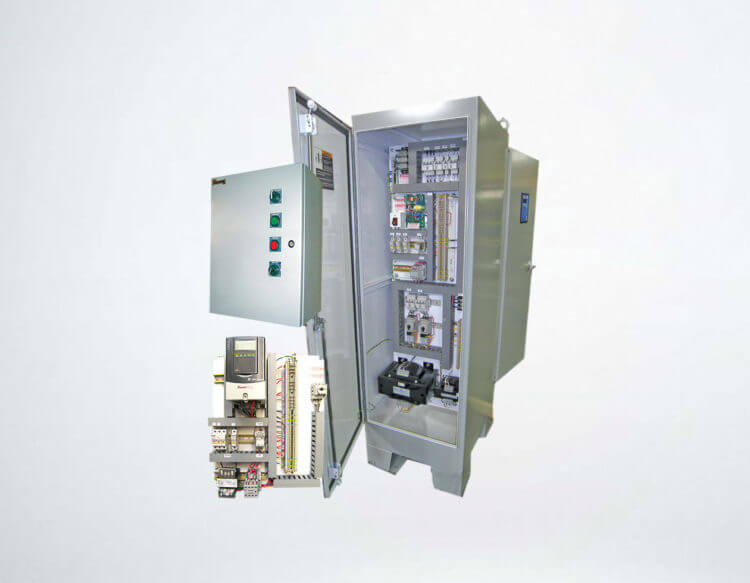
| – Open Chassis: | Type IP23, 8.0″ H x 6.0″ W x 4.5″ D (203.2 x 152.4 x 114.3 mm) |
| – Enclosed: | Type IP66, 11.81″ H x 9.84″ W x 5.91″ D (300 x 250 x 150 mm) |
Agency Approvals
– Underwriters Laboratories, UL File #E208487
Standard Input/Output Specifications
| – Analog Input: | 2-wire Loop powered Range: 4-20 mA typical (30mA max.) Input Impedance: 169 Ohm Voltage drop: 3.38V typical (5.1 max.) Resolution: 22 bit AI-1 Programmable, Field Selectable |
|
| – Analog Output: | Isolated 4-20 mA into 750 Ohm Load Maximum Sourcing, +24VDC Compliance Voltage, Range 0-24 mA Resolution 16 bit AO-1 Programmable, Field Selectable |
|
| – Digital Inputs: | Require Dry Contact Closures Sourcing, +12VDC with 10 mA Minimum Sink Current DI-DS Discrete – Drive Status DI-1, 2, 3 Programmable, Field Selectable |
|
| – Digital Outputs: | Isolated Relay Outputs DO-1, 2 Form A, 140 VAC/ 200VDC @ 0.05A, 14 VAC/20 VDC @ 0.5A, Contact Rating 10W, Resistive load Programmable, Field Selectable DO-3 Form A, Solid State Relay, 240 VAC/VDC, 100 mA maximum. Programmable, Field Selectable Remote Totals Form A, Solid State Relay, 240 VAC/VDC, 100 mA maximum. |
|